From Fixturing to Job-Ready Mesh. One Guided Workflow.
A closer look at how Rotary Scanning works in Augmentus.
Every Robot Path Starts With a Model of the Real Part
Every robotic finishing, spraying, or welding job depends on an accurate 3D model of the workpiece — the toolpath is only as good as the geometry it is generated on. And the model has to cover the whole part, not just the side facing the sensor. For parts that already sit on a rotary positioner — pipes and flanges, pressure vessels and tanks, wheels and rims — capturing that full geometry used to mean repositioning the sensor pose after pose and stitching the results together.
The Part Turns, the Scanner Captures
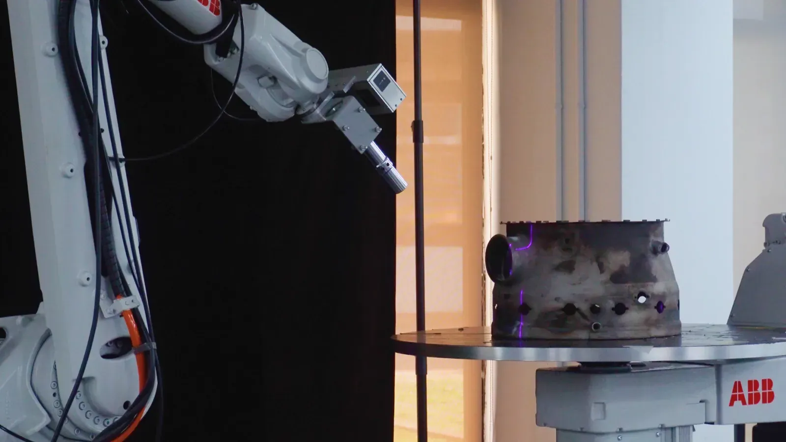
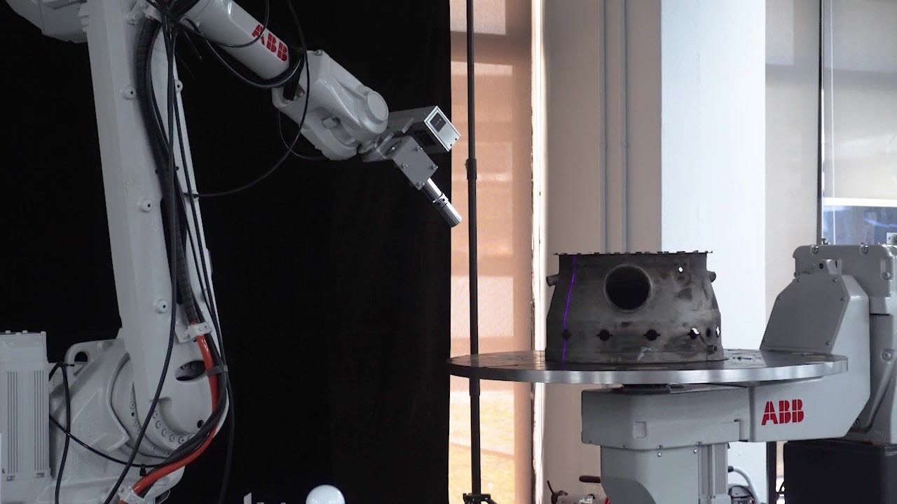
Rotary Scanning takes the motion the cell already has and uses it for capture: the part is mounted on the positioner and rotated while the scanner captures continuously. The result is a complete mesh of the part, built as it turns.
- Faster scanning — the positioner rotates continuously instead of the arm stopping and re-posing pose after pose.
- Better coverage of detail — the scanner holds its standoff and angle while every face of the part rotates through its field of view.
- Fewer scan passes — most parts are captured in a single continuous rotation; larger or more complex parts add passes, and the software stitches them into one model.
Rotary Scanning is built for positioner-mounted, rotationally symmetric parts. For occluded, multi-face geometry, Robot Scan approaches from any angle; for long parts, Linear Rail Scan travels the length — and the modes can be mixed and stitched into one unified scan.
Rotary Calibration Is a Guided Routine, Not a Specialist Task
Before the first scan, the software needs to know exactly where the rotation axis sits relative to the robot and the sensor. What used to be a specialist task is now a short guided routine: place the calibration jig at the center of the turntable, and the software auto-positions the sensor, runs a coarse calibration pass, then refines it — mapping the rotation axis and locking the sensor, positioner, and robot arm to one reference frame. The routine typically takes around 5 minutes.
The calibration is also inspectable, not a black box: the routine saves the raw calibration scan and a calibration report, so the measured geometry can be verified against the jig's known dimensions before any production scan runs.
Set the Position, Set the Coverage, Run the Scan
Setting up the scan itself is a short checklist rather than a programming task. Position the sensor with the workpiece in its field of view, choose Fast or Accurate mode, and leave mesh resolution on Auto unless the job calls for manual control. Set the coverage — a full 360 degrees for most parts — and run.
From there the software does the rest: the laser sweeps the part as it rotates, the captured passes are stitched into a point cloud, and the reconstructed mesh opens in the Mesh Editor, where stray points can be lassoed and removed in a few clicks. The output is a clean, job-ready mesh of the actual part on the actual fixture.
From Scan Straight to Robot Motion
A CAD file has to be aligned to the physical part with a 3-point calibration before programming. A rotary scan skips that step: because the sensor, positioner, and arm share one calibrated reference frame, the mesh is captured directly in the cell's coordinate system — the model is already where the part is.
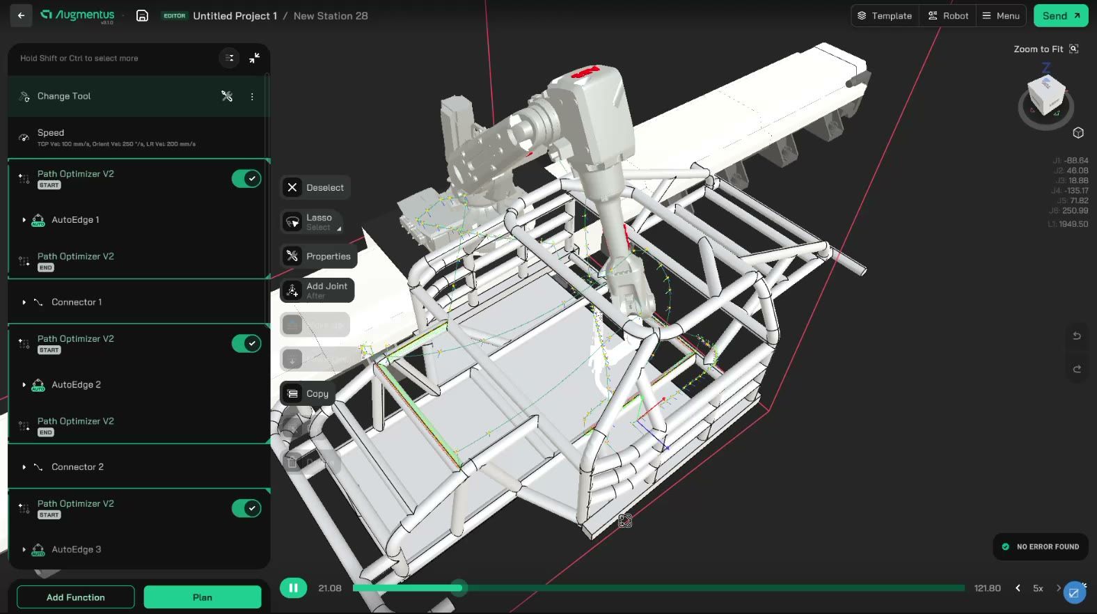
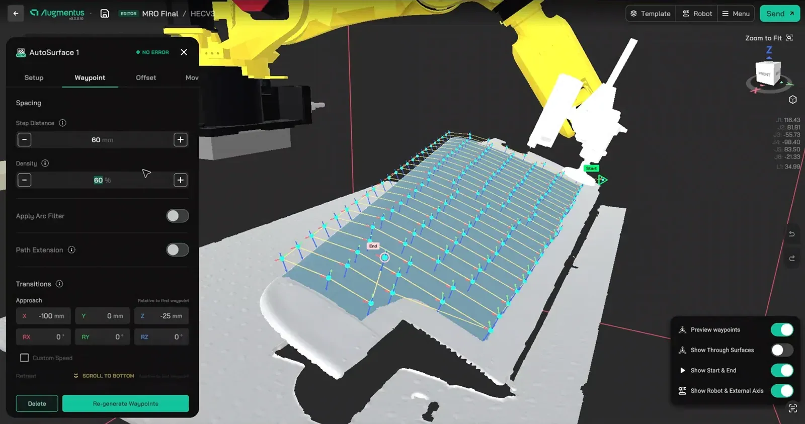
That means the scan feeds straight into path generation. AutoGen generates toolpaths directly on the scanned surface: AutoSurface for area coverage, AutoEdge for edges and rims, AutoPattern for repeating layouts — with no export, conversion, or cleanup in between. The model you capture is the model the robot runs against.
A More Direct Path From Fixturing to Running the Job
For end users, Rotary Scanning removes the gap between mounting a part and programming it — no CAD file to source, no manual alignment, no scanning specialist on call. For system integrators, it means delivering full-coverage scanning cells on the positioner hardware the cell already uses, without complex repositioning sequences or extra floor space.